Characteristics and operation
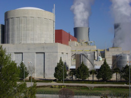
The Cofrentes nuclear power plant (Cofrentes NPP) is equipped with a Boiling Water Reactor (BWR/6), manufactured by General Electric, with a brute electrical power of 1,092.02 MW.
The Boiling Water Reactor is of the direct cycle sort, i.e., there is a single fluid or primary coolant that vaporizes in the reactor or nuclear furnace.
Cofrentes NPP is a second generation, and is the only plant using boiling water technology in Spain, since the rest use pressurized water reactors.
Key facts
BWR/6
Reactor type
3,237
Thermical power (MWt)
1,092
Electrical power (MWe)
2
Cooling loops
UO2
Fuel
624
Fuel elements
110Tn
Uranium weight
145
Control rods
24Months
Operational cycles
Júcar river
Natural draft towers – Cooling system
3
Turbine units
20kV
Voltage at the alternator terminals
1975
9th september
Building permit
1984
23rd August
1st criticality
1984
14th October
1st coupling
1985
11th March
Commercial operation
Description of operation
To generate energy, the system requires a steam-producing mechanism, and this is the reactor core, which is located together with auxiliary elements and control within a pressurized vessel where there is a constant fission of uranium atoms producing the heat required to vaporize the water.
The fuel utilized in this process is a slightly enriched uranium (4.2%) as the isotope U-235, in the form of a synthesized oxide (UO2). This constitutes a ceramic material, capable of sustaining elevated temperatures and radiation doses, contained in hollow rods made of Zircaloy-2 (zirconium alloy) grouped in turn in sets of 11×11 rods creating easily handled fuel elements.
The steps involved to obtain energy by this process are:
WordPress database error: [Table 'linprod.wp_imagelinks' doesn't exist]SELECT * FROM wp_imagelinks WHERE id='1'
Error: invalid imagelinks database record
The 20 kV from the generator are enhanced to a voltage of 400 kV in the main transformer bank. This transformer bank comprises 3 single-phase units with a power rating of 3 x 361 MVA and a 20/400 kV transformer relation. Their outlet is connected to the 400 kV farm for subsequent energy distribution to the power grid.
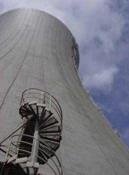
The plant is cooled by means of a closed circuit through two natural draft towers standing 129 metres high with a base diameter of 90 metres. The water reaches the tower by closed tubes from the main turbine condenser cooling system and is cooled as it falls pulverized by the counterflow of rising air. The water then leaves the base or reservoir of the towers by an open channel to the all-weather outdoor circulation pump house, where 4 helical pumps, with a vertical shaft and 2,800 HP of unit power, propel a cooling flow of 33.000 m3/hour to the condensers, thus closing the circuit.
The reactor’s level of power is regulated by the recirculating pumps and the control rods that penetrate the core from underneath.
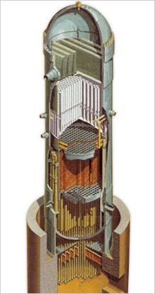
The reactor’s pressure vessel, made of highly resistant, low-alloy carbon steel, stands 21.8 metres high and has an effective interior diameter of 5.5 metres. Further, the vessel has been designed, manufactured and tested in accordance with the relevant ASME code, Section III, Class I; which certifies that the minimum wall thickness is 15.2 cm with an interior stainless steel 5mm-thick coating.
- Vessel cover
The dismountable upper semi-spherical cover, manufactured from the same material as the vessel, allows access to its interior during maintenance or for when changing fuel.
- Steam dryer
The steam dryer enhances the quality of the steam generated by the separator, as much as 99.9 %, creating a seal between humid steam from the separator and dry steam, which goes to the turbine.
In fact, this is an intricate piece forming a single-pieced unit lacking moving parts.
- Moisture separator
The separator constitutes the first and foremost phase in improving the quality of the steam, increasing it from 15 % up to 90 % to its outlet from the core. This cylcone-type system (without moving parts) is welded to the vertical pipes of the shroud cover.
- Jet pumps
This is an internal vessel component designed to produce a forced moderator-coolant circulation through the core in order to enhance the reactor power when compared with natural circulation. The twenty stainless steel jet pumps are mounted in symmetrical groups of two around the core shroud.
- Control rods
The control rods are devices that render uniform distribution of power by regulating the core’s reactivity. These are set up so as to compensate steam bubbles (holes) in its upper portion, hence providing an important levelling to the power distribution curve. There are 145 control bars inside the core arranged crosswise, and each cross section is formed by 18 tubes of either stainless steel or boron carbide (CB4), which contains the neutron-absorbing material. The estimated duration of usage for each one of these rods, taking gas expansion into account, is 15 years, and an estimated nuclear life of 18 years for 10 % loss of reactivity control.
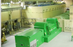
The turbine harnesses the steam’s thermal energy to produce mechanical energy. The main turbine is the motor that activates the generator and it thus supplies the rotor with sufficient mechanical power to satisfy the demands of the grid load, maintaining a frequency of 50 Hz.
The turbine at Cofrentes NPP turns at 1,500 rpm and is furnished with a steam by-pass rated at 35 % of its capacity, which thus allows start-up and compensates the instantaneous load variations at minimal alterations in steam pressure
The reactor core comprises 624 fuel elements that contain 110 t of Uranium with an average enrichment grade of 4.2 % as isotope U-235.
Each fuel element is formed by bars of approximately 1 cm in diameter and 3.8 metres in length placed vertically and fixed to both ends by two structures or support plates, plus seven intermediate spacers. Each element is encased in a zircaloy-4 squared-section sleeve or channel.
Besides fuel elements and adequate measuring devices, the core also contains 145 control rods that penetrate the core from underneath. These are stainless steel cross-slotted rods containing boron carbine enriched with the isotope B-10, a neutron-absorbing material.
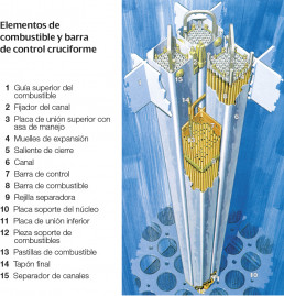
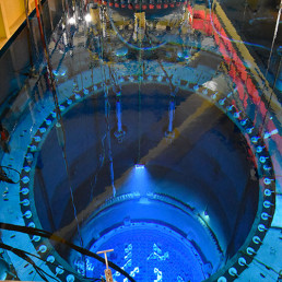
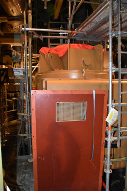
The reactor core is housed within the pressurized vessel, where it is fixed in an adequate position by the lower support plate and the guide (upper plate). It is cooled by means of forced convection from 2 recirculation pumps run by a motors (2 x 6,400 HP) outside the vessel, and a ring of 20 jet pumps inside the reactor vessel around the core.
The Cofrentes NPP is currently furnished with a titanium Condenser manufactured by ABB Alstom, which came to replace the original copper-nickel model, and is a multipressure double-bodied type model with 43,300 tuber per body for cooling water flow of 111,000 m3/h.
The condenser is in closed circuit cooling with the natural draft towers, which cool when fully loaded with a water flow of 32.8 m3/seconds.
The condenser tube cleaning system, manufactured by Taprogge, operates by means of 8,000 balls through the tubes.
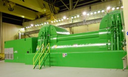
The mechanical energy present in the turbine is transformed into electrical energy in the main generator, manufactured by General Electric, with 1,120 MVA of nominal power with a power factor of 0.9 and 1,500 rpm, to a voltage of 20 kV and frequency of 50 Hz.
The maximum current of the generator extractor is from 34,034 A and from 5,488 A for the rotor.
The generator is cooled by hydrogen and the plant’s service water.
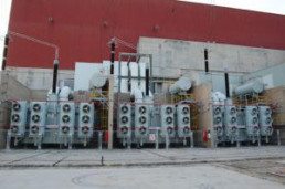
The generator’s energy output of 20 kV is received by 3 single-phase transformers with a no-load turns ration of 20/400 kV, from where it is conveyed to the farm at 400 kV on the double busbar with switch and a half, and four 4 outlets to the energy grid plus 2 reserve outlets.
The current transformers were actually manufactured by ABB, and installed in the Plant in 2005 and 2007, which both modernized and enhanced efficiency.
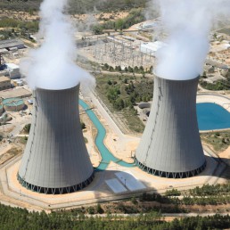
Cofrentes NPP is cooled by means of a closed circuit through two natural draft towers standing 129 metres high with a base diameter of 90 metres.
The water cooling the main turbine’s condenser, at a temperature of approximately 42 ºC, is fed to the towers through closed piping, where it is elevated 12 metres through the centre, to be cooled by allowing it fall and pulverize against a counterflow of rising air coming from the lower part of the tower.
The water is then collected at the base or reservoir of the towers, where it is then sent via open channel to the outdoor circulation pump house, where 4 helical pumps, with a vertical shaft and 2,800 HP of unit power, propel a cooling flow of 33,000 m3/hour to the condensers, thus closing the circuit.
The recirculation system is made up of two circuits of recirculation pumps outside the reactor vessel. These circuits constitute the path for the water flow to the jet pumps inside the vessel.
The reactor power can vary in power intervals of up to approximately 40 %, affecting the reactor’s recirculation flow, and consequently the core flow.
Change in flow alters the content of the holes in the core, consequently varying the power (a change in the proportion of holes imply a variation of volume in the moderator).
To vary this flow, Cofrentes NPP utilizes a pressure control valve (FCV) when discharging each recirculation pump.
